SYSTEM 2-Channel Balance controller/Dimmer for MeanWell
Assembly instruction: SYSTEM 2-Channel Balance controller/Dimmer for MeanWell
Overview
working time
15 min.
difficulty
beginner
Steps
5
1 Dimmer connection
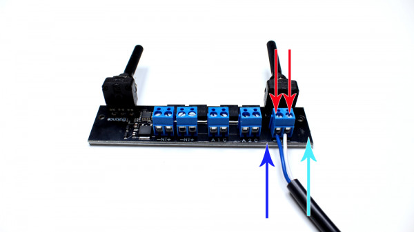
"+" dimmer cable
"-" dimmer cable
The dimmer cable is connected via the blue socket labeled +DIM- and can be regulated via the potentiometer labeled DIM.
2 Connect power supply
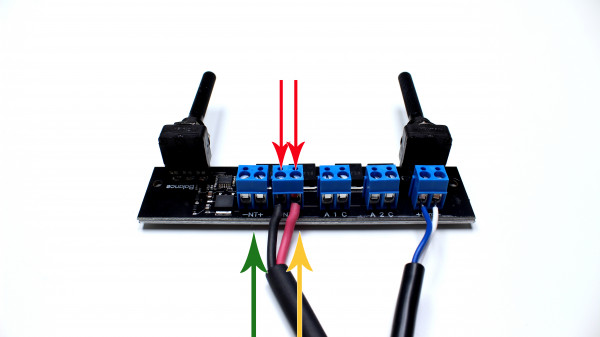
"-" minus power supply
"+" plus power supply
For the power supply of the LED modules, two connectors are available on the controller module which are each labeled with -NT+. The connections are parallel.
3 Connect Channel 1 and Channel 2
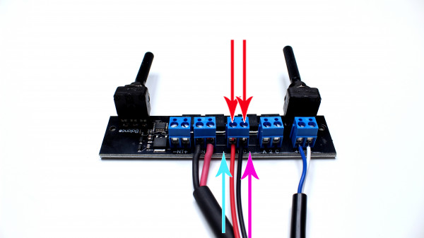
Anode (+) Channel 1
Cathode (-) Channel 1
Anode (+) Channel 2
Cathode (-) Channel 2
The first channel of the board is connected via A 1 C, the second channel via A 2 C, where A stands for anode (PLUS), C for cathode (MINUS) and the number 1 or 2 for the respective channel.
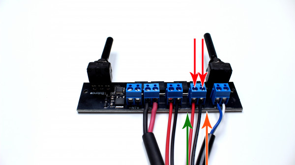
4 Connect LED module
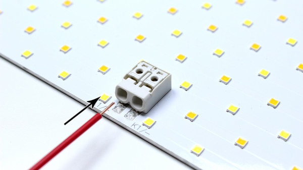
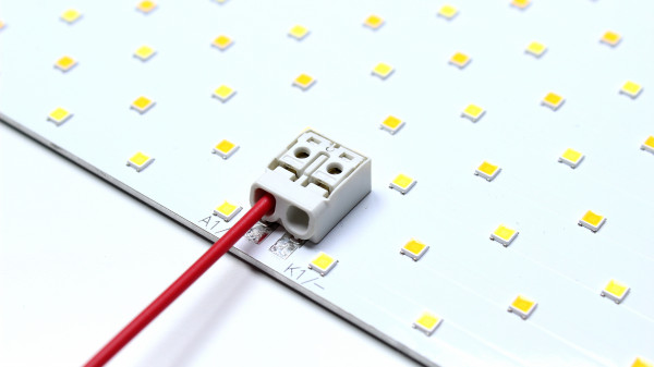
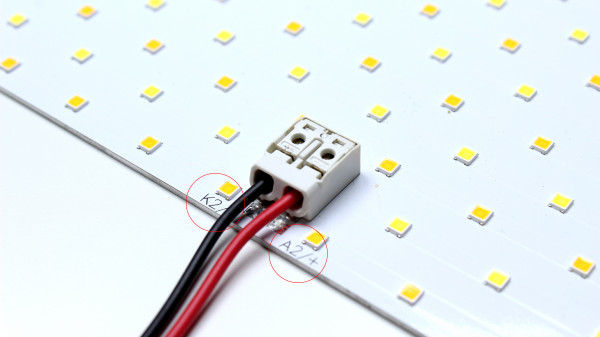
Simply insert the stripped conductor (anode (+) channel 1) into the terminal point as far as it will go. The wire is automatically and securely clamped.
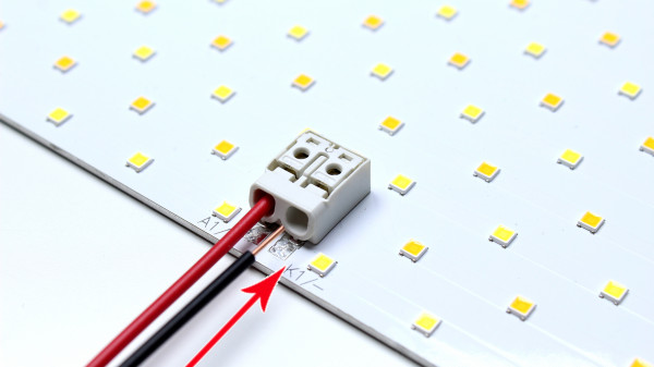
Insert the stripped conductor (cathode (-) channel 1) into the terminal point as far as it will go. The wire is automatically and securely clamped.
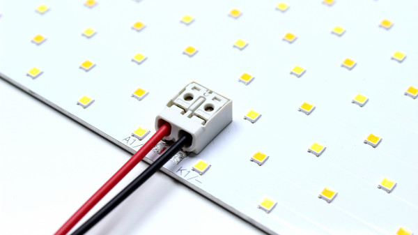
Connect the second channel using the same principle.
5 video
© LED-TECH.DE - Disclaimer: Mounting and operating only by qualified (electric-)staff. We do not assume any liability.