Mounting connector (4x3) box
Assembly instruction: Mounting instruction of a 90x90cm DIY-240W-KIT
Overview Page backward Page forward
working time
10 min.
difficulty
beginner
Steps
6
1 Prepare material
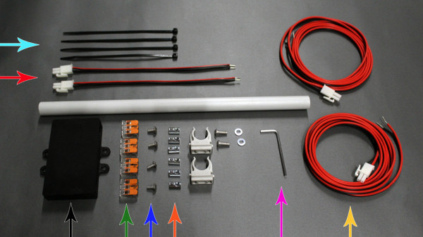
Material list picture 1
4 x black zip tie
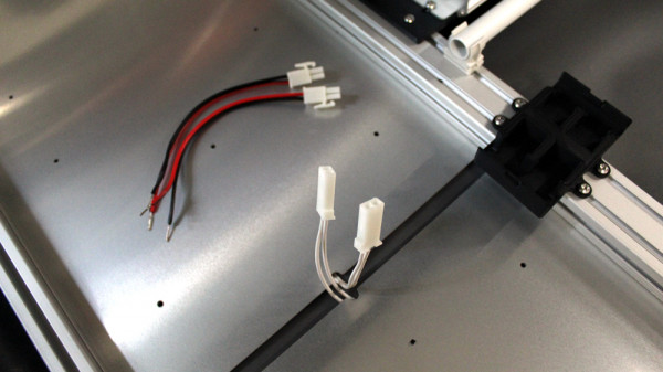
2 x Inputcable (15 cm)
SYSTEM Box for Wago
4 x COMPACT-Connection terminal WAGO 221-413
4 x M4x8mm lens screw
6 x M4 slot nuts
2,5mm hex screwdriver
2 x Inputcable (60 cm)
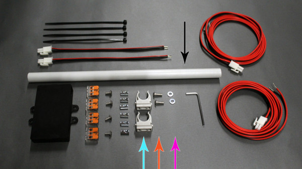
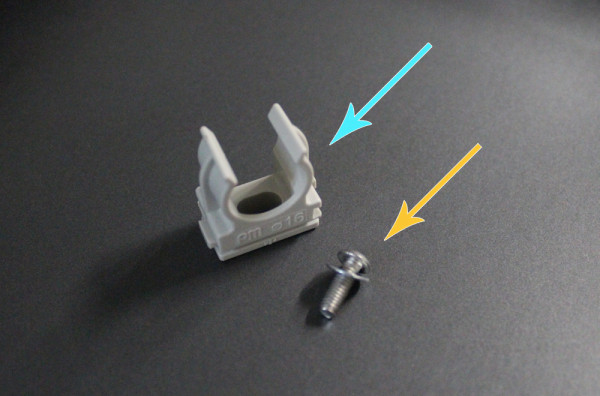
Material list picture 2
1x Cable duct (round tube) 16mm - length: 31cm
2x mounting clip for 16mm round tube
2 x M4x12mm lens screw
2 x M4 washer
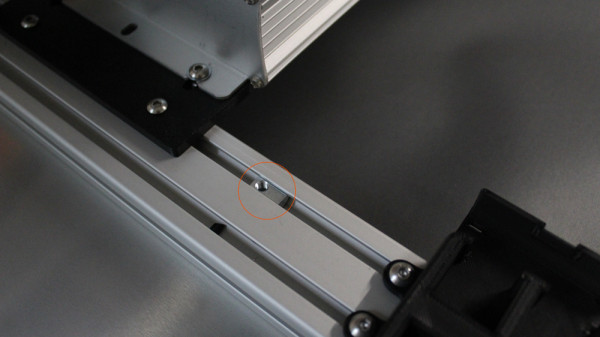
2 Insert slot nuts
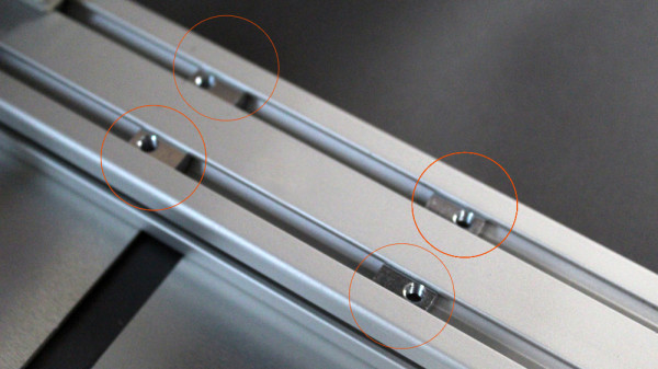
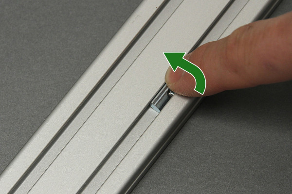
Insert the slot nuts into the orange marked positions. The following steps explains how to insert the slot nuts from above into the profile.
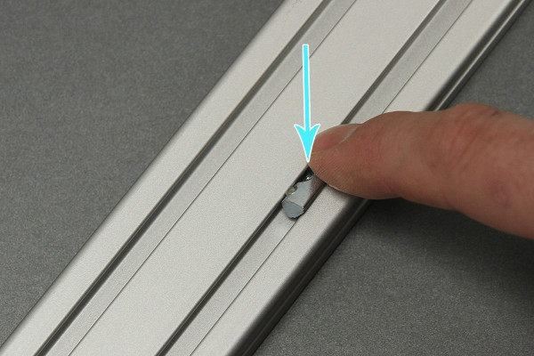
Press the slot nut sideward into the profile.
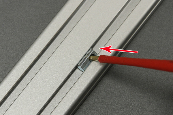
After inserting, please tilt the slot nut in the right position like shown on the photo.
Insert a small screw driver into the slot nut. Please be carefully, don't damage the thread!
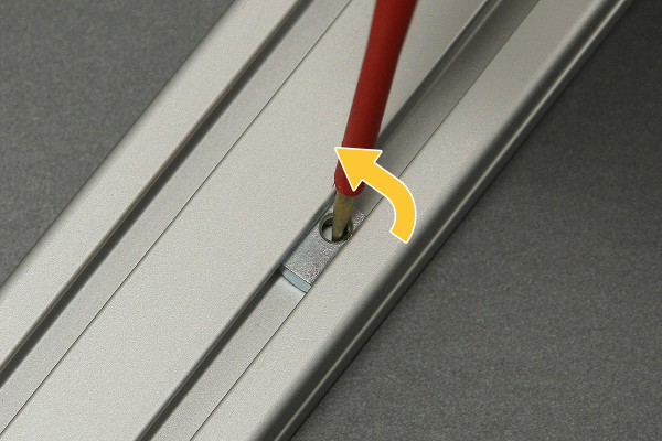
Now turn the screw driver carefully so that the slot nut turn upwards inside the profile.
3 Mount housing
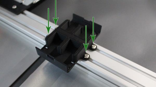
Tighten the "SYSTEM Box for Wago" with M4x8mm screws. For tighten use the 2,5mm hex screwdriver.
4 Mount the cable duct
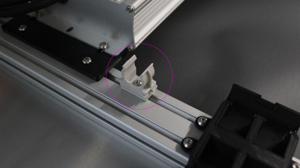
Mounting clip for 16mm round tube
Screw M4x12 | washer M4
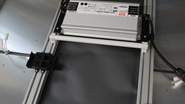
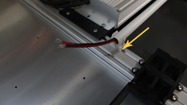
Insert the slot nut into the profile and position it between the power supply unit and the Wago protective box.
Fasten the mounting clip for 16mm round tubes with the M4x12 screw and the M4 washer on the profile.
Repeat the step on the opposite side of the frame.
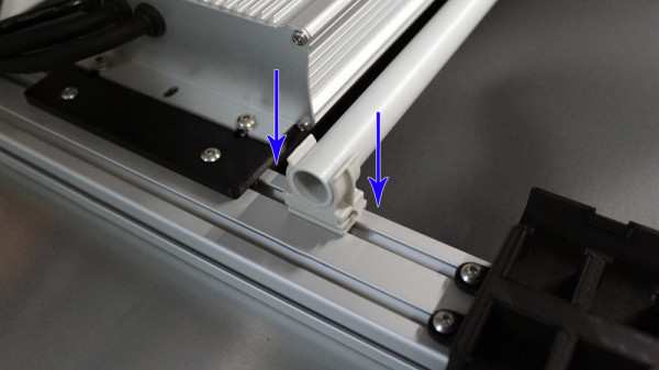
Plug the cable duct (16mm round tube) onto the two mounting clips.
5 Connecting wires
Risk of electric shock / Risk of injury! Installation only by persons with relevant electrotechnical knowledge and experiences. By inappropriate installation you danger your own life and the life of the users of the electrical system.
Disconnect the cables before working on the product, disconnect the fuse and secure it against being switched on again.
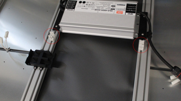
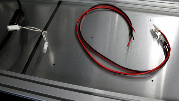
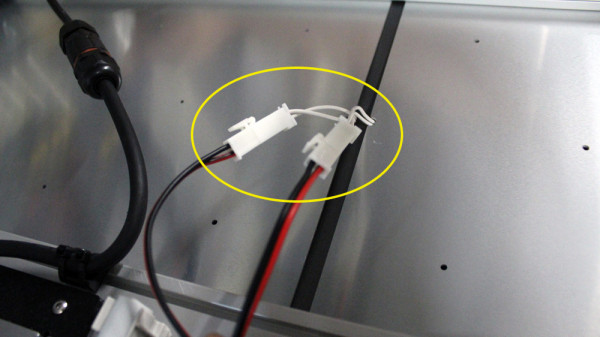
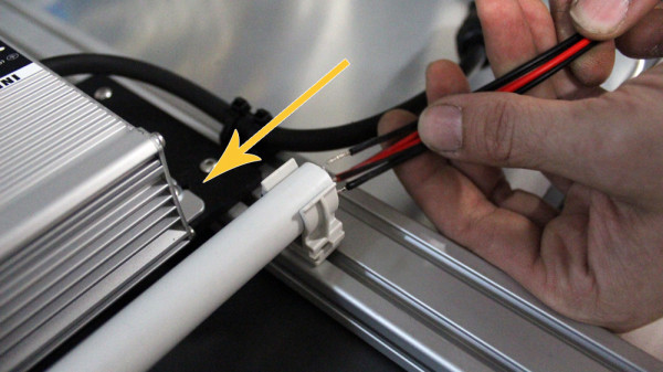
Connect the 60cm long feeder cables to the boards and then run the cables through the cable duct.
Connect the 15cm long power cable to the boards and run the cables to the Wago protection box.
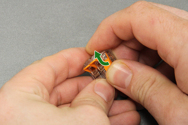
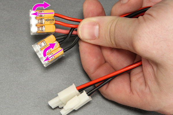
Open the Wago-clamp.
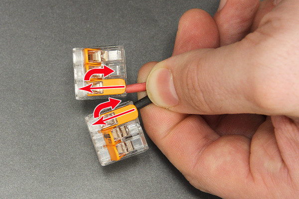
Insert the "Output" cables of the power supply (labeled on the power supply as OUTPUT V+ and V-), like shown on the photo, into the Wago clamp. The cable must be inserted till the end of the clamp and it must be closed afterwards.
Take the first inputcable. Insert the red wire of the inputcable near the red wire of the "output" cable of the power supply into the wago clamp and close it afterward. Repeat this process with the black wire.
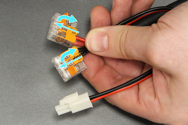
Repeat this process with the second inputcable. All red wires and all black wires are in one Wago-clamp now!
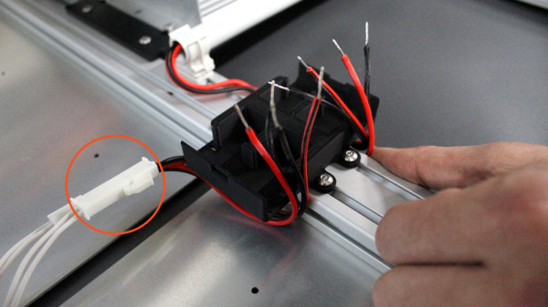
6 Insert clamps
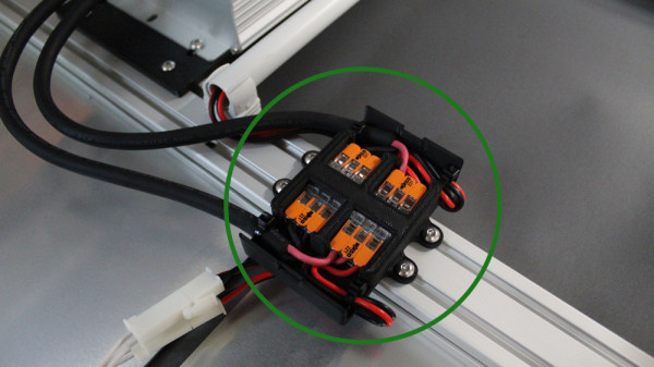
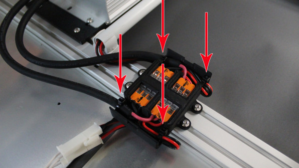
Insert the Wago-clamps into the housing and arrange the wires like shown on the photo.
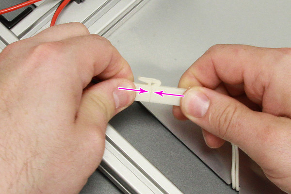
Insert the zip ties through the zip tie holders.
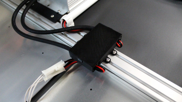
Shorten the zip ties with a site cutter.
Put the cover again on the SYSTEM Box.
© LED-TECH.DE - Disclaimer: Mounting and operating only by qualified (electric-)staff. We do not assume any liability.